

CHAPTER 13 — Metaphors to Drawing
18-minute read

Perspective in perspective
Albrecht Dürer was known as the “da Vinci of the North” because he was fascinated with, and contributed to, the relationship between art and science. Like da Vinci, he was not only a skilled draughtsman but an inventor as well. He applied his energy to elaborate drawing “machines” that could capture perspective, the way of seeing that defined Renaissance image-making. We can still make and use these machines today.
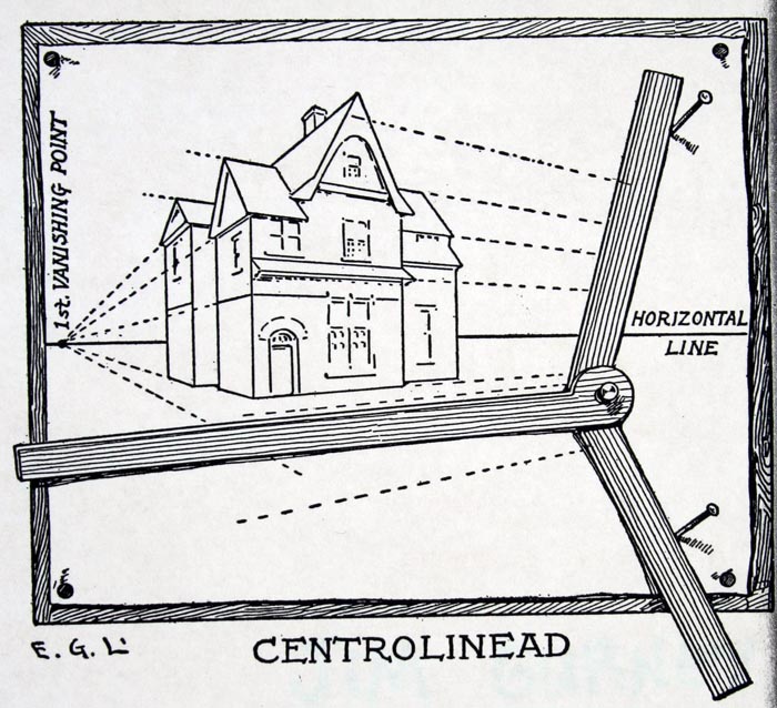
Mechanical drawing devices, like the T-square and triangle, the parallel bar, and the drafting machine all depended upon a drafting board. They allowed us to create the complex mechanics of one-, two-, and three-point perspective systems. Technology solved many of the limitations of the drafting board. The centrolinead, for example, was developed to orient remote vanishing points requiring an improbably large surface. The knowledge gained about perspective as a system by using these elaborate mechanical tools is easily transferable to sketching.
Why bother?
But why would we want to even bother with any of that? These systems and tools may seem quaint when discussing a digital interface and its use. After all, the machine is processing so much of the mechanics of projection for us. This relieves us of the dirty work of constructing a perspective matrix or a set of orthographic drawings. Yet, the illustration below demonstrates precisely why it’s a necessary topic!
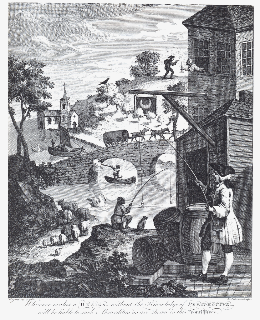
William Hogarth, Satire on False Perspective, 1753. The caption in the engraving reads: “Whoever makes a Design without the knowledge of Perspective will be liable to such absurdities as are shewn in this Frontispiece.” This remains as true for computer modeling and rendering as it has always been for tactile media.
The structure of the visible world
The laborious methods required to create, for example, a two-point perspective image are no longer necessary. However, with their loss as a process, we risk a loss of understanding of what these systems physically encode in drawing. This includes visual principles of composition, strategies for visually structuring an object or an environment, and pragmatic mental tools for aiding digital workflow. As tedious as these processes might have been, they allowed us to see, in their construction, the structure of the visual world.
These drawing “machines” — perspective drawing, drafting, sketching, and modeling — produced very specific output and yielded specific means of 3-D visualization. Software is simply an extension of these machines. Most 3D modeling software is capable of showing you views of your work in all of the projection modes we will discuss! Software is thus, at one level, a mash-up of all prior drawing tools. Despite that, the software behaves as a unique and new tool. Like those other drawing machines when they were introduced as new technologies, digital modeling tools are fundamentally changing the way we see the world.
Projection: rival geometries
More-than-three dimensions
… physicists do not study just the 3-D space we live in. There are … spaces which have totally different geometrical properties from the physical space within which we live. Who is to say, then, that “the true geometry” is defined by the space in which Uranus and Neptune orbit the sun? There is “Hilbert space,” where quantum-mechanical wave functions undulate; there is “momentum space,” where Fourier components dwell; there is “reciprocal space,” where wave vectors cavort; there is “phase space,” where many-particle configurations swish; and so on. There is absolutely no reason that the geometries of all these spaces should be the same; in fact, they couldn’t possibly be the same! So it is essential and vital for physicists that different and “rival” geometries should exist.
— Douglas Hofstadter
Humans don’t perceive the fourth dimension the way we perceive three-dimensional space. We can move freely up and down in height, for example, but we can only move in one direction — forward — in time. So when physicists and n-dimensional geometers discuss the full reality of the fourth dimension, they must resort to visual analogy. To see a tesseract (a four-dimensional cube) as we do in the illustration above, we can animate it. But even this does not get us to a complete understanding of what the tesseract is in dimensions we ourselves are not privileged to move freely in.
Dimensions by analogy
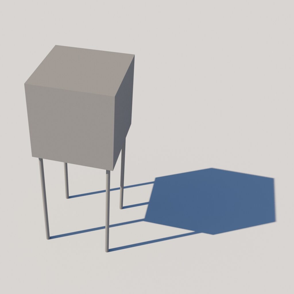
An analogy: imagine the experience of seeing a shadow of a cube on the ground. If we can rotate the cube, we can see the shadow change shape. However, unless we can fully perceive the cube, the rotating shadow gives us only a limited understanding. The shadow on the ground is a Projection of a three-dimensional reality onto the two-dimensional surface of the ground. The best way to “read” the illustration, then, is to imagine the rotating tesseract as the projection of a four-dimensional reality onto the three-dimensional world we can perceive without restriction.
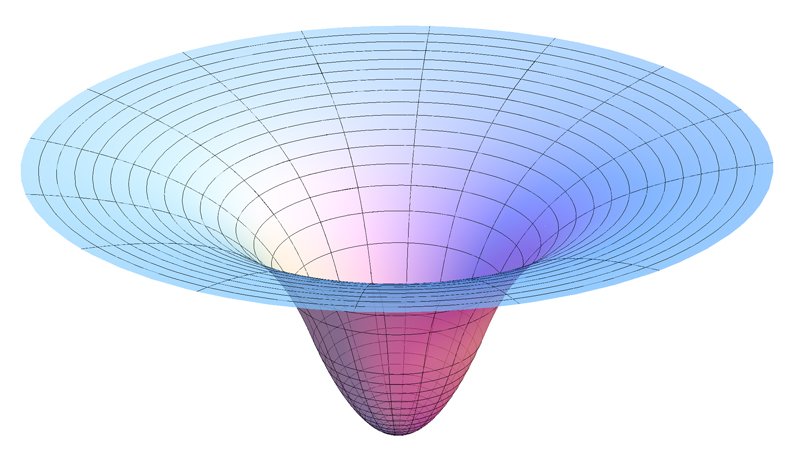
Another example of projection helps us understand the higher-dimensional reality of gravity’s effect on the fabric of space-time. Physicists project an idea of four-dimensional space-time onto a plane, which deforms under gravity’s influence. It’s like a large, stretchy sheet of rubber would behave if we placed a bowling ball on it. Of course, it’s absurd to think of the Sun sitting on a large, deformed plane. But if we see the plane as a projection of a 4D world, the analogy makes sense.
Rivals — or allies?
The current state of the computing interface only allows a modeler a projected view of work. At minimum we find ourselves developing a 3D environment projected onto the 2D surface of the monitor. And, if animating, it becomes worse as we add the fourth dimension! We find ourselves in the shoes of the physicist who is trying to understand a projection of a rival dimension into one we can perceive. But we do have one advantage: we can use our experiences of space and time to help us understand the projected reality of the world we are modeling. That poor physicist will never get to experience a truly higher-dimensional world.
We’ll explore two ways the concept of projection informs modeling. We’ll see how perception and representation have been informed by projection from the beginning of art. From this, we’ll understand how using projection drawing systems in 2D representation can be of fundamental pragmatic use in 3D modeling. It turns out these are not rival, but rather complementary, geometries.
Projection: the origin of art
In his blog projection systems, Pablo Garcia writes extensively on projection as
both a technique and a conceptual framework. As a representational method, it refers to the use of lines or vectors, usually straight, to translate between two- and three-dimensional information. Conceptually, it refers to a way of thinking about 3D space and its representation, relying on empirical methods; non-arithmetic and precisely articulated information that is graphically manifest. … Projection spans back to our earliest times, using shadows and celestial objects to assist humans in the depiction and manipulation of our environment. As such, the study of projection is the study of virtual reality. Since cave paintings and, later, celestial alignments of monolithic structures, and, later still, the early science of Ancient Greece, virtual reality — the ability to re-present real-world data graphically — has been a critical element of what made humans elevate beyond our ancestors.
— Pablo Garcia
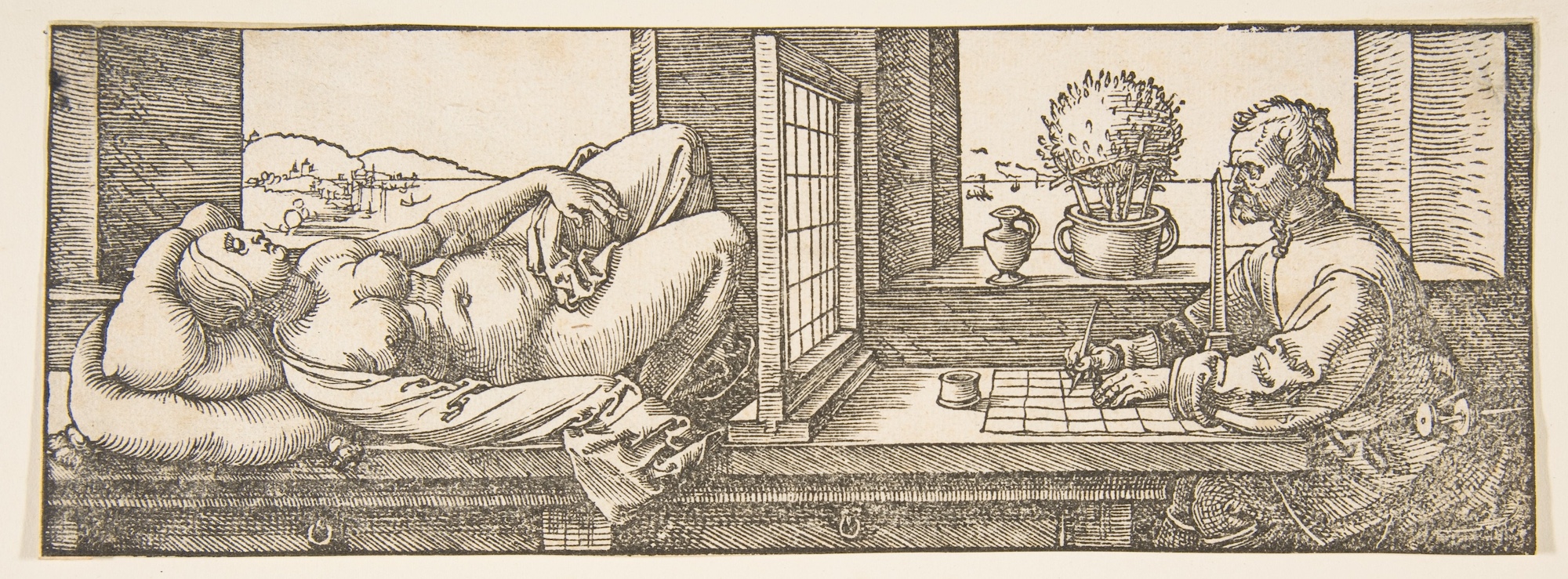
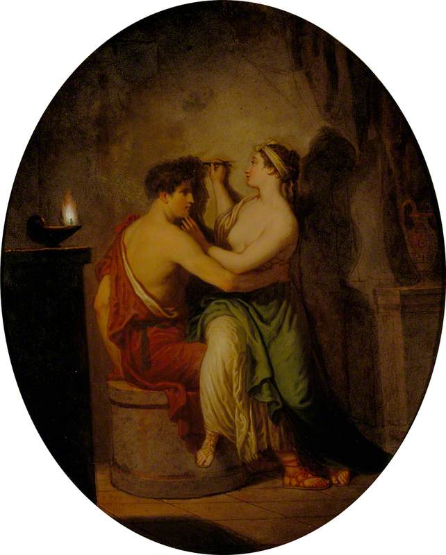
Could it be that projection is the origin of art? Consider this fable presented by Professor Garcia. Pliny the Elder, an officer of the Roman Empire and author, recounts in his Natural History the tale of an ancient Greek artist and the origin of painting:
Butades, a potter of Sicyon, was the first who invented, at Corinth, the art of modelling portraits in the earth which he used in his trade. It was through his daughter that he made the discovery; who, being deeply in love with a young man about to depart on a long journey, traced the profile of his face, as thrown upon the wall by the light of the lamp. Upon seeing this, her father filled in the outline, by compressing clay upon the surface, and so made a face in relief, which he then hardened by fire along with other articles of pottery.
— Pliny the Elder
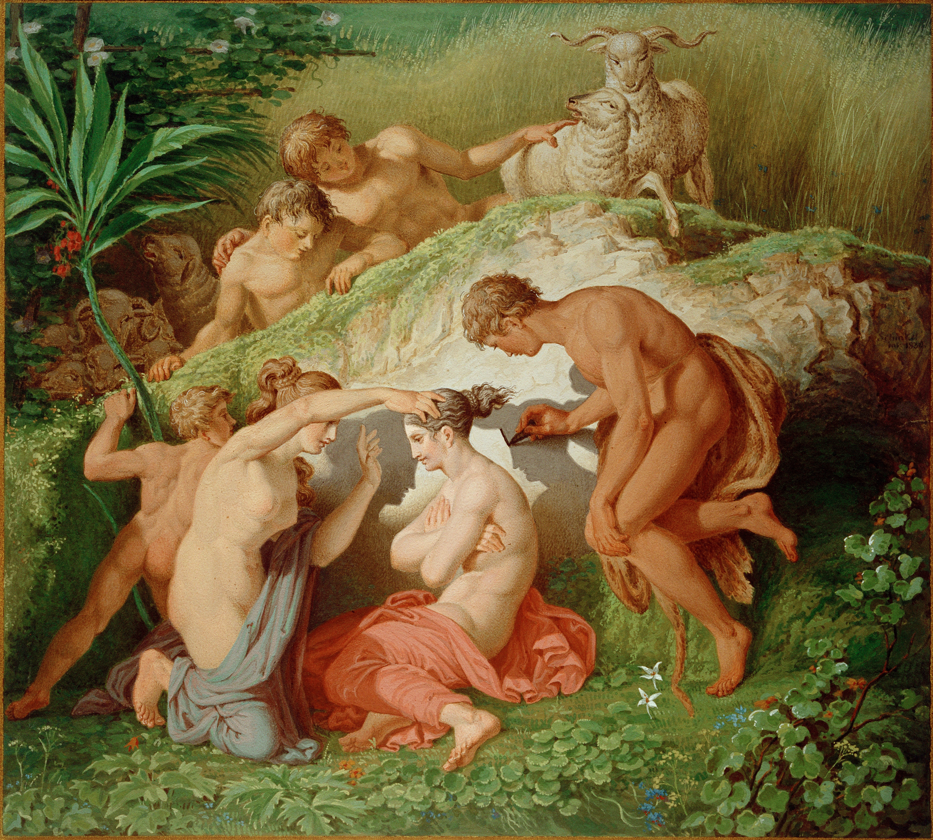
Discussing Butades, Professor Garcia references architectural historian Robert Evans, who
… in his essay “Translations from Drawing to Building” makes an astute observation regarding the Schinkel version shown above. In comparing it to David Allen’s rendition, he notes that Schinkel, an architect, is the only of his contemporaries to depict the shadow as cast by the sun. Allen and others use the point source of a lamp. Evans uses this discrepancy to explain the two major paradigms of projection: parallel (orthography) and centric [perspective] projection. The artist uses the converging lines to make enlargements and reductions in the scale of the image, by changing the physical relationships between light, subject, and wall. The architect requires precision in scale for transmission of information. The sun provides this control, so it doesn’t matter where the subject is; the sun’s rays are parallel, guaranteeing a precise same-scale reproduction when the shadow reaches its screen.
— Pablo Garcia
As we’ll discuss below, you will use parallel projection drawing strategies to create orthographic image planes for 3D model creation. You will also use concepts from perspective projection to create camera views for representing the finished model. In 3D modeling, understanding both becomes a critical skill.
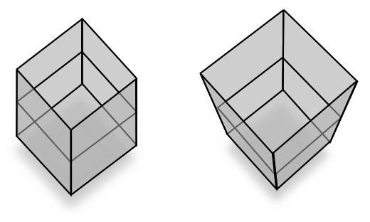
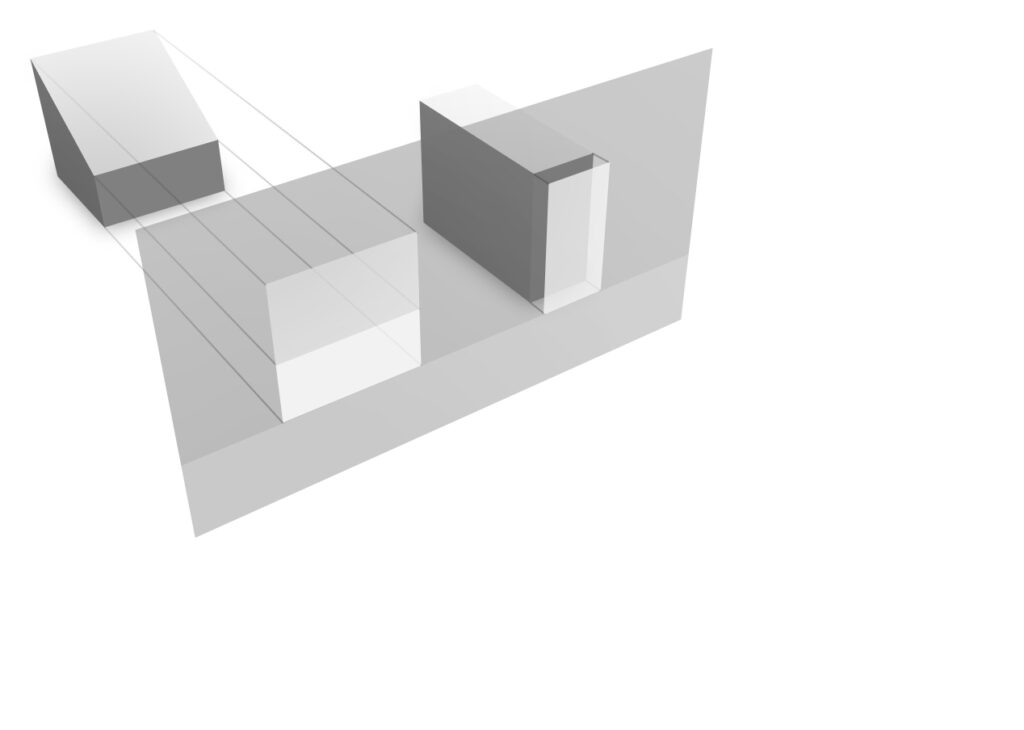
The parallel projection of a cube on the left displays no perspective foreshortening, while on the right it is seen with perspective foreshortening.
We can see the relationship between parallel and perspective views in this animation. A parallel projection corresponds to a hypothetical perspective projection where the camera lies an infinite distance away from the object and has an infinite focal length. The modeling viewport can manipulate views such as this. The animation cycle starts with a three-point perspective and ends with the type of parallel projection known as an isometric.
Projection: drawing systems
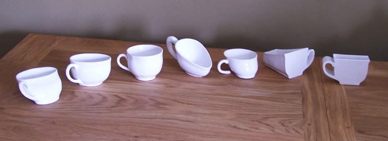
A traditional discussion of projection systems leads from simple line drawings to highly complex perspectives. But mechanical drawings are deceptively abstract. Because perspective very closely approximates the way we naturally see the world, it makes more sense to approach the topic of projection systems from the more familiar, less abstract position. We can then work our way “backward” to pure orthographic drawing. We’ll first look at why it’s even necessary to know about these systems in a post-drawing world. Then we’ll follow by looking at perspective and parallel projection methodologies and how they express themselves in the 3D modeling user interface. Like Erica Gohdes’ teacups, these projections constitute many ways of looking at one thing, each useful in their turn.
Perspective projection
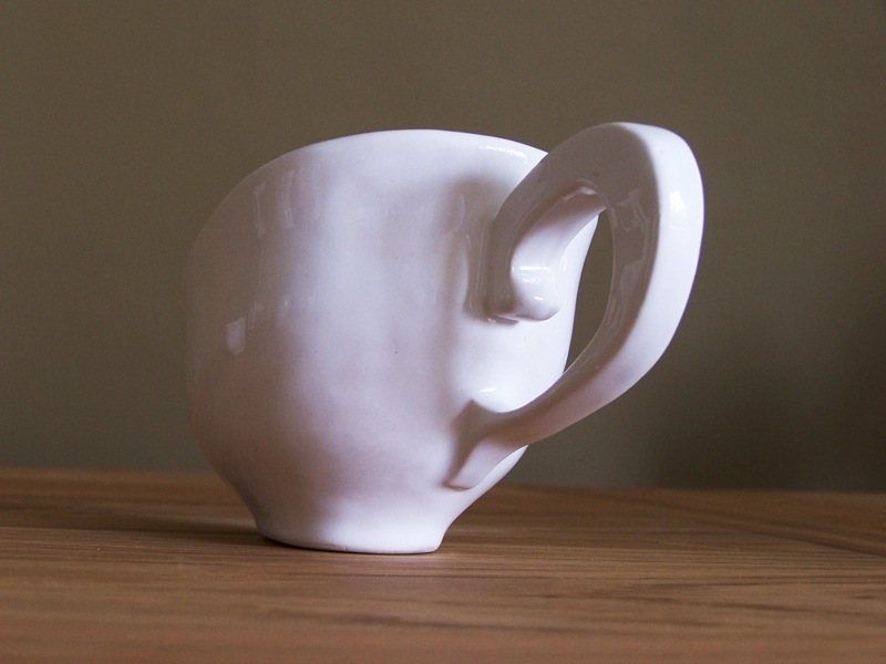
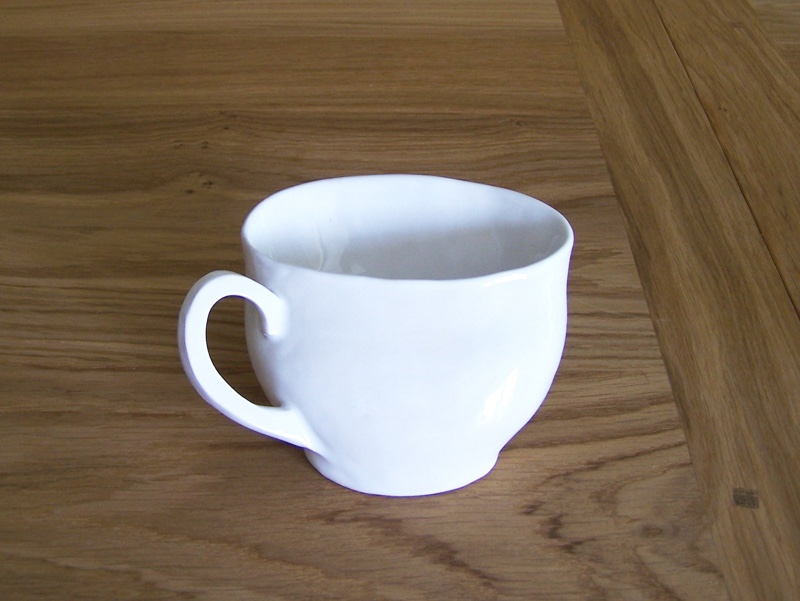
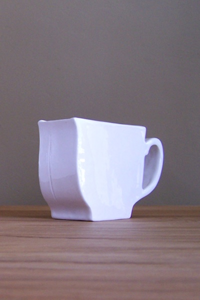
Erica Gohdes, Reading Between the (Out)Lines, 2007.
Erica’s Perspective Cup seems stretched because she’s placed a fixed perspective view back into “our” perspective matrix. We can use this technique to create a “forced” perspective seen in a stage set design and the optical illusion found in an Ames Room.
Perspective is a “natural” way to see the world. But it’s a very unnatural and difficult thing to construct! This possibly explains why it was not until the early Renaissance that the mechanics of human optics were systematized in drawing. Before the Renaissance, artists attempted intuitive suggestions of objects receding in space in a non-systematic way. Either that, or perspective was ignored altogether in favor of equally valid systems of hierarchic scale, symbolic, or abstract representation.
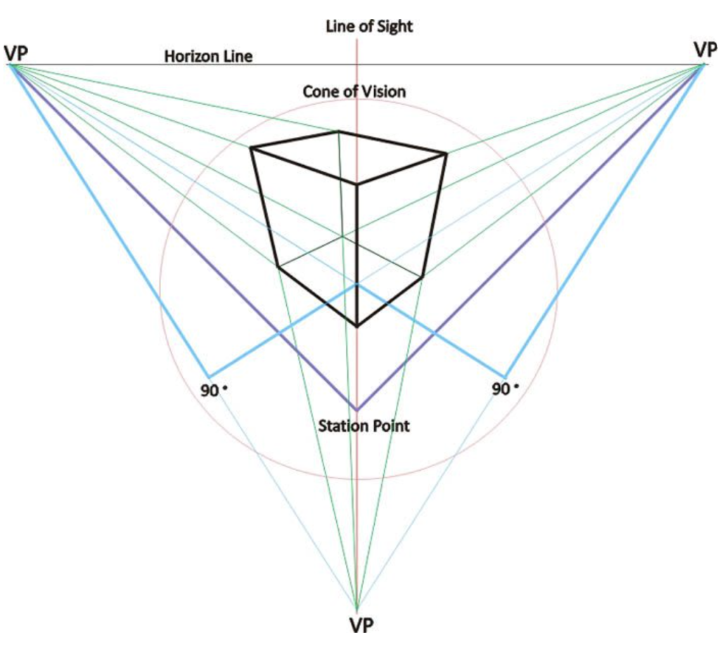
The humanist worldview of the Renaissance — the human being is the center and measure of all — allowed artists such as Filippo Brunelleschi, Leon Battista Aberti, and Albrecht Dürer to conceive of the components of a perspective matrix. These include a station point where the viewer stands, a picture plane that captures images of objects as they travel along lines of sight to the viewer, and vanishing points along a horizon line coincidental with the height of the viewer’s eye. All of these refer back to the particular point of view of an individual spectator.
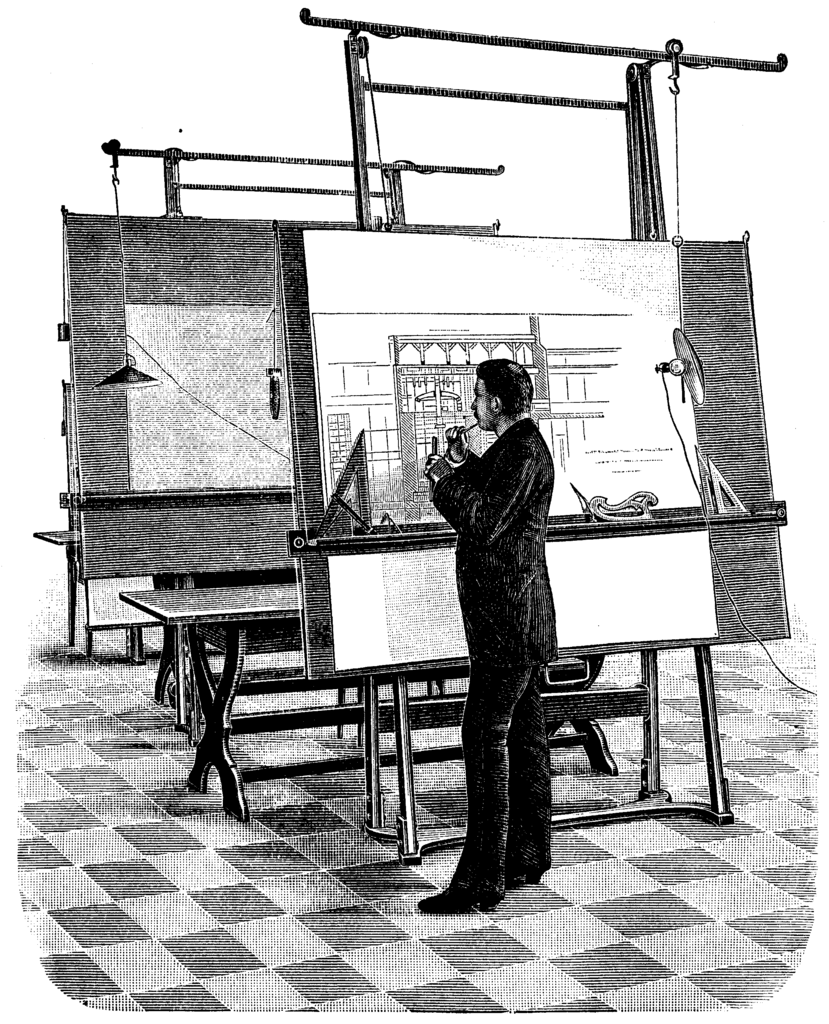
Mirrors and windows
The development of perspective was aided by the invention and use of several technologies that make these abstractions relatively tangible, as seen below:
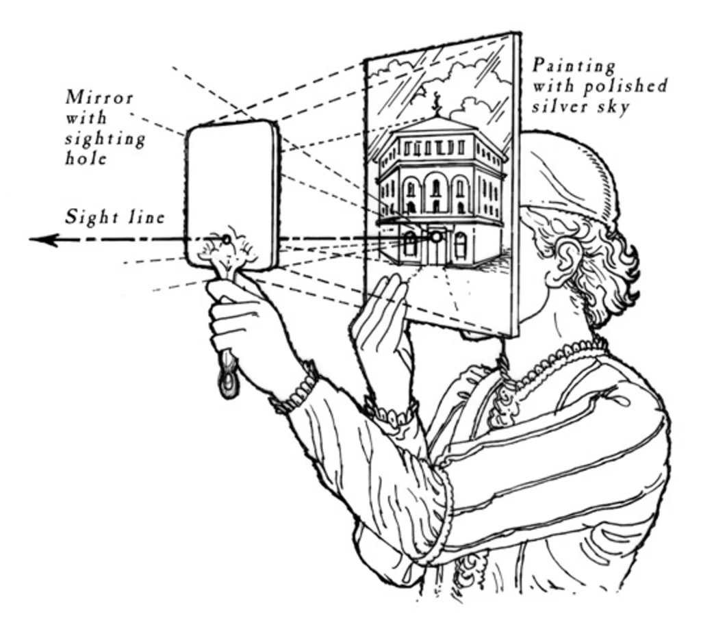
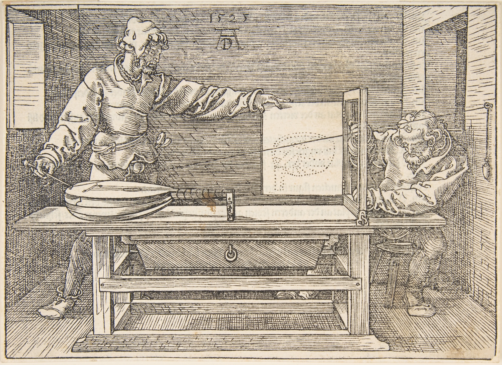
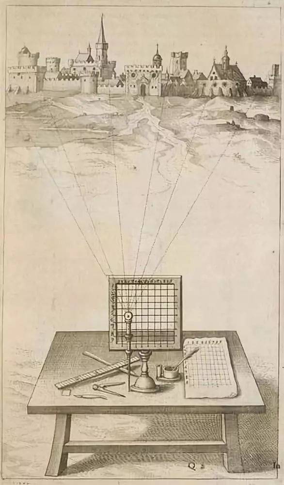
A picture plane
These devices made a tangible, screen-like expression out of the picture plane, not unlike the viewport on your monitor. But the simplest way to think of the picture plane is as a window onto a view. As Leonardo da Vinci described the new system, “Perspective is nothing else than the seeing of an object through a sheet of glass, on the surface of which may be marked all the things that are behind the glass.”
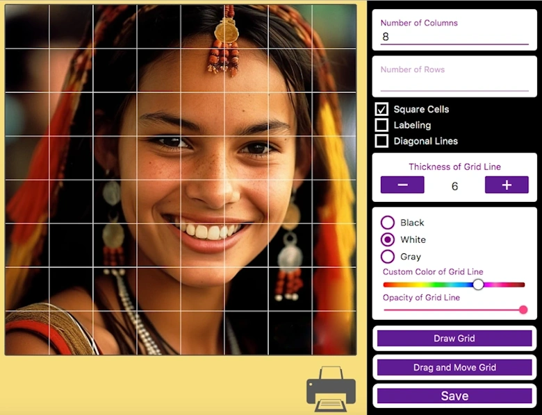
An easy way to experience the expression of a picture plane is to use an actual window. Using a grease pencil, draw a border approximately 9” by 12” on the window. Stand in one spot, close one eye, and without moving your position, draw the outlines of what you see inside the border. When you step away from your station point, you will see you’ve created exactly what you would on your paper or canvas by using an abstract picture plane. Once you’ve tried a few different windows and views, you will understand the term “picture plane”.
In addition to your computer monitor, some modern expressions of the picture plane on mobile platforms:
Georgia Tech Augmented Environments Lab and Savannah College of Art and Design, ARhrrrr, 2009. A prototype augmented reality first-person shooter game using a mobile camera phone. Pro: gets you off the couch. Con: encourages you to play with your food.
Three-point perspective
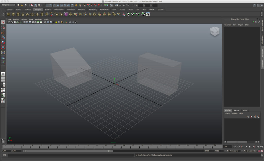
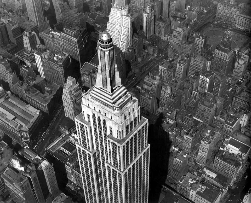
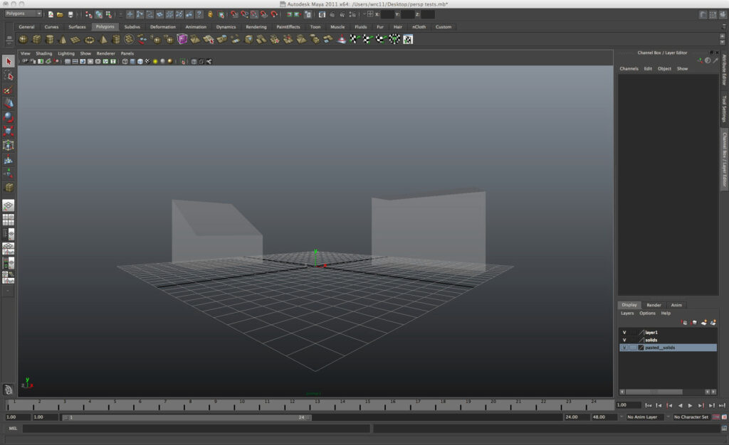
When you first open a 3D program, you may encounter a view from a camera oriented toward a Three-Point Perspective view. You can recognize a three-point projection any time you see the verticals in your modeled volumes sloping in or out, skewed against the orthogonal edges of the viewport. Whenever the direction of your point of view (in the modeling UI, the camera) is not parallel to the ground plane, the resulting view is three-point. Aerial (a.k.a. bird’s-eye) or ground (a.k.a. worm’s-eye) views result from tipping the head up or down to view.
But this kind of view is more common than the unusual view from an airplane down to skyscrapers. Even looking down at objects on a tabletop is a common manifestation of three-point. The relatively rigid, perfectly level viewing orientation needed to achieve two-point projection makes it less common in day-to-day experience than you might think.
Two-point perspective
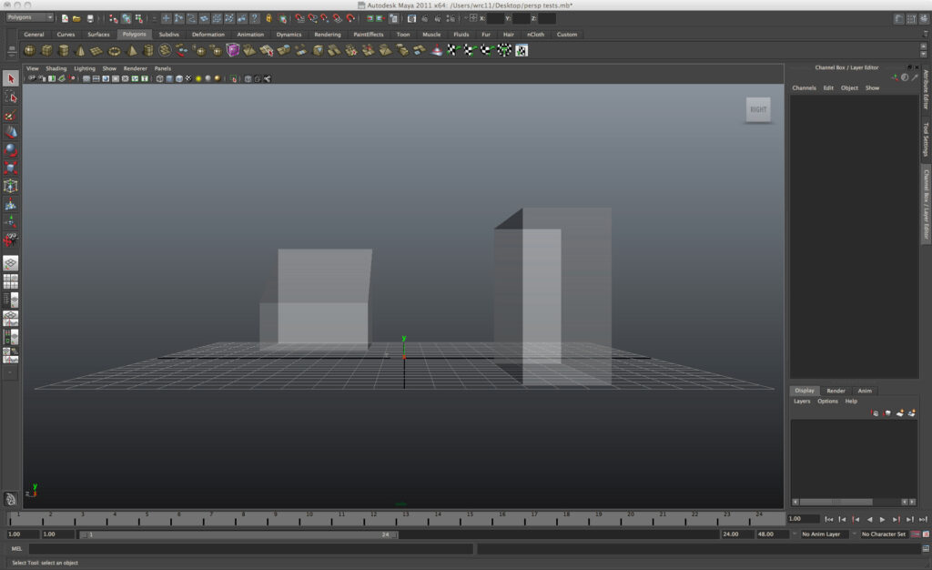
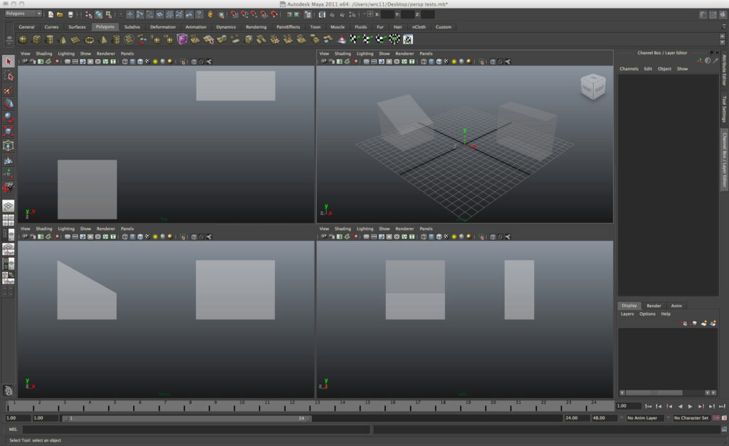
Compare the view in the illustrations. In the first, we see the same camera lowered to a position about 5 feet off the XZ reference plane — eye level for a standing human — and rotated to be perfectly parallel with that ground plane. These are the conditions necessary to achieve a Two-Point Perspective. Even though this way of looking at the world is highly structured, it sometimes feels more “natural” to us than the more common three-point experience. We are upright creatures used to looking at the world with our eyes, on average, gazing at the horizon. This is why we regard photographs with pictorial verticals parallel to the upright edges of the composition as aesthetically pleasing. Again: a proper two-point perspective is created ONLY when the camera line of sight is parallel to the ground plane.
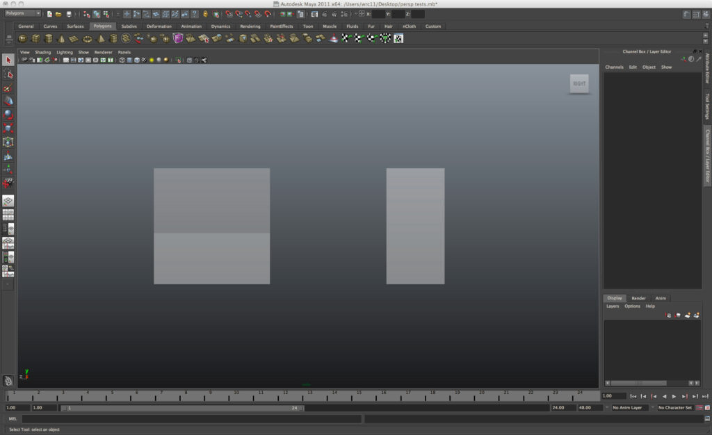
One-point perspective
Compare the illustrations. The point of view has now been shifted so that the direction of the camera is perpendicular to the right sides of the masses. The resulting picture plane is parallel to them. This creates a One-Point Perspective view. This kind of perspective is beloved by designers and painters of interior scenes, as it lends stability and comprehensibility to the masses and voids of defined spaces. A Left, Right, Front, or Back view in the UI will automatically create a one-point view. A Top or Bottom view will also create a one-point, looking straight up or down instead of at the horizon.
Parallel projection
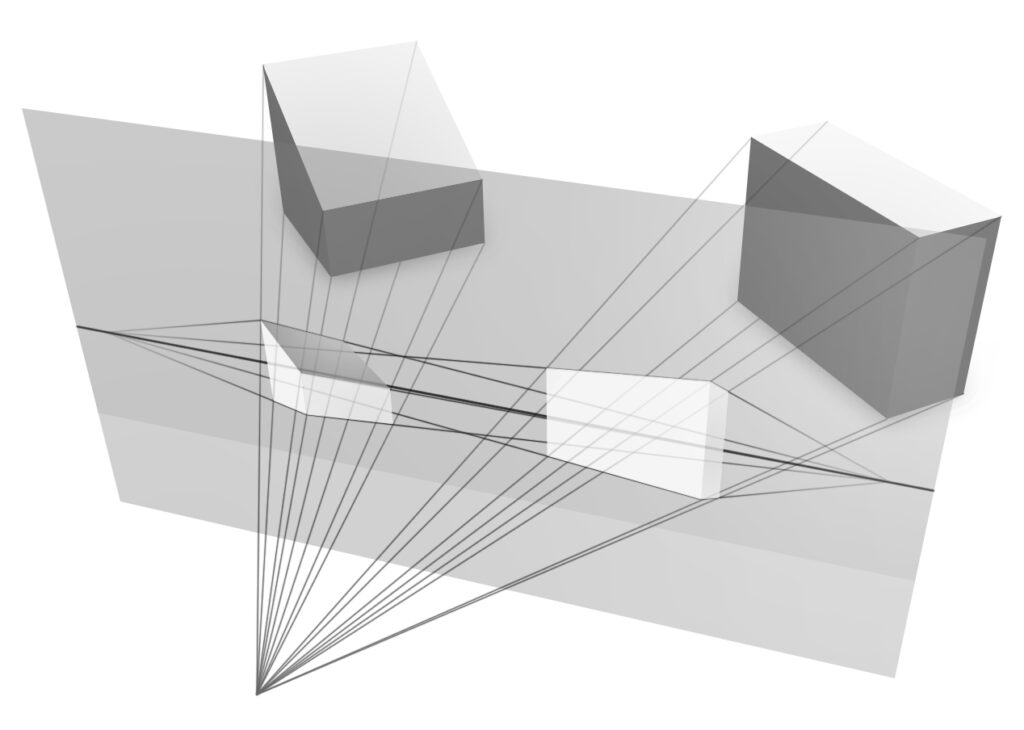
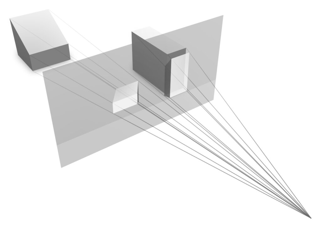
In perspective projection, as the illustrations demonstrate, the lines of sight from the objects pass through the picture plane and converge on a single point. As you might guess, in Parallel Projection, the lines of sight are parallel with each other as they project to the picture plane. By definition, they never converge. When we set a camera in a modeling program with Perspective off, it renders a parallel projection through that camera. Parallel projection is useful when a sense of dimension, proportion, or aspect ratio needs to be maintained as a model gets built.
Zero-point “perspective”
If you’ve ever taken a photograph with a telephoto lens, you know this reduces the sense of depth in your shot, but it increases your ability to see very far. Turning Perspective off in a program’s virtual camera creates a strange, hyper-telephoto perspective projection with a theoretical viewpoint in which the camera stands at an infinite distance away from the object and has an infinite focal length or “zoom’ (recall this is illustrated above). You’ve entered the strange world of Zero-Point “Perspective,” another name for parallel projection. It is a complete abstraction — no such hypothetically “infinite” camera exists — but as we will see, it is a highly useful one.
Parallel projections are used to create views known as Pictorials, which in the viewport are seen in Axonometric Projection. They are also used to create Orthographic Projections in drawing form, which the viewport can both emulate and use.
Axonometric projection
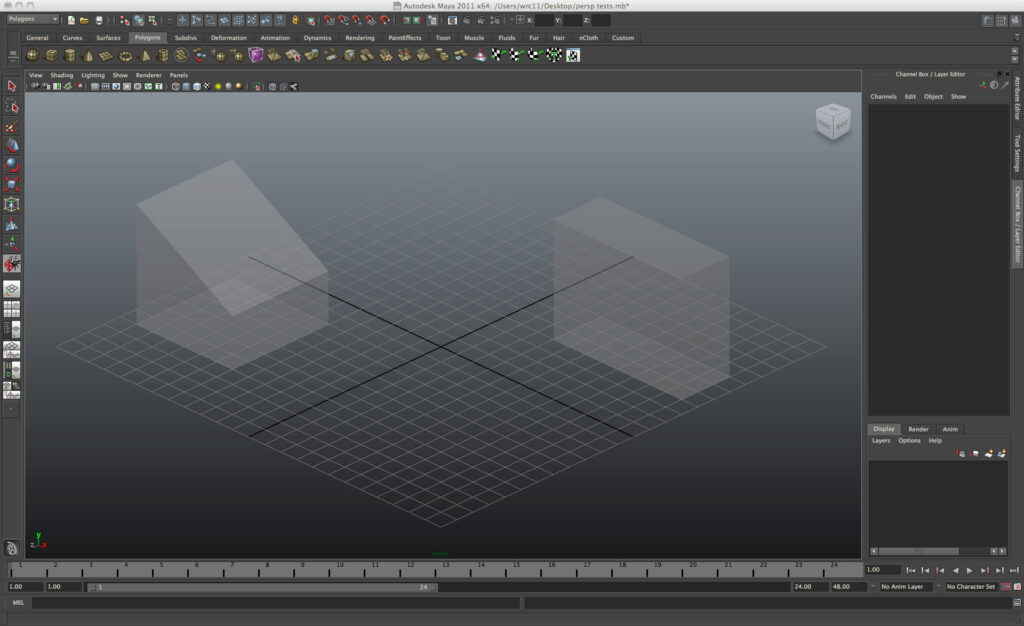
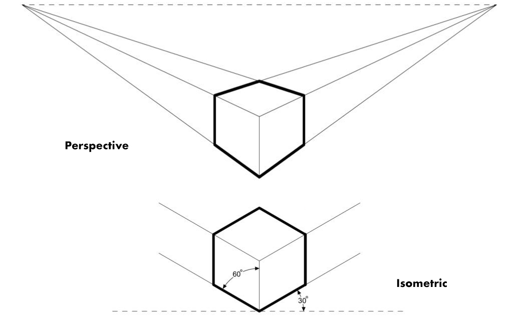
An Axonometric Projection is a pictorial view wherein the planes and axes of an object are not parallel to the picture plane so that more than one side of the object can be seen. A special case of axonometric typically seen in the viewport is known as an Isometric Projection, characterized by either a 60∘ or 120∘ angle to represent a 90∘ angle found in reality. This was systematized in the West around the beginning of the 19th Century, but according to Jan Krikke, its function as a spatial device originated in ancient China, where it was used as the equivalent of perspective in the West. It later found a home in the woodblock prints of Japan.

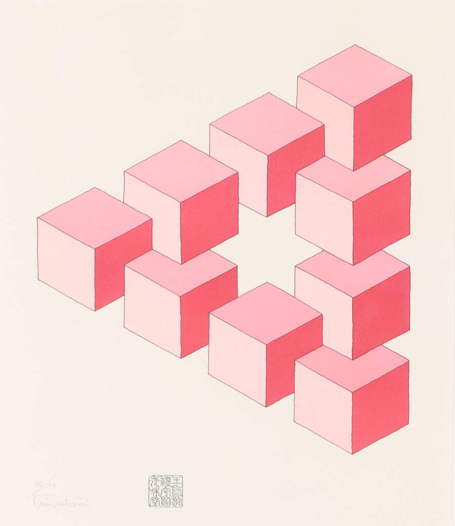
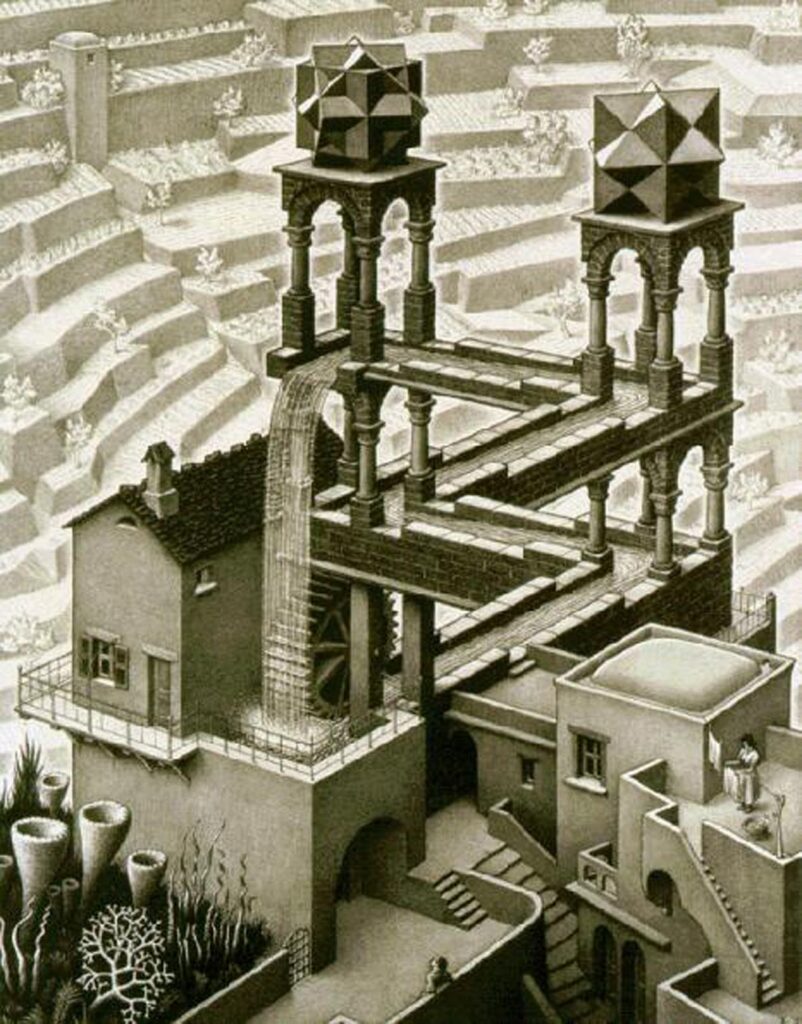
“Impossible” shapes
One special property of axonometric projection is spatial ambiguity. This allowed artists to develop so-called “impossible” shapes in the early and middle 20th Century. Oscar Reutersvard, the father of the impossible shape, expressed them as pure geometric worlds, whereas M. C. Escher created plausibly habitable impossibilities like his Waterfall, though his drawings are distorted slightly out of isometry. Because it is easy to process algorithmically, isometry became very popular in games such as Will Wright’s SimCity. The elegant Echochrome paid tribute both to Escher and the traditional use of isometric game space.
Sony Entertainment, Trailer for Echochrome, 2008
Oblique and orthographic projection
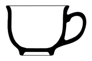
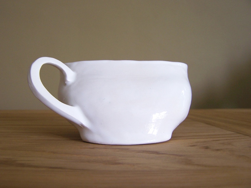
Erica’s Orthographic Cup appears to be the extrusion of the profile of the cup — and that’s precisely what it is!
Pictorial geometries have a peculiar property: while linear measurements are undistorted, angular measurements are. This occurs because either:
- the picture plane is not parallel to the faces of the object — the axonometric view — or …
- 2) the angle of projection is not perpendicular to a picture plane parallel to the object, a parallel projection known as Oblique.
If, on the other hand, the picture plane is parallel to the faces of the object, and the angles of projection are perpendicular to the picture plane, this is known as Orthographic projection.
“Glass box” animation by Dennis Lieu
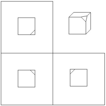
Orthographic projection is the preferred choice for making technical drawings and architectural plans. That’s because it contains no angular or linear distortion. Measurement, and a certain way of perceiving Cartesian space, are facilitated by creating projection relationships in multiple orthographic views. In these, a plan or top view aligns vertically with an elevation or front view. This in turn aligns horizontally with another elevation or side view. The standard four-view viewport in Maya emulates this orthographic organization, known as “third-angle” projection. Third-angle drawings present an object as if several orthographic projections of an object were performed on the faces of a glass cube. This cube unfolds flat to facilitate a drawing view, seen conceptually in the video here.
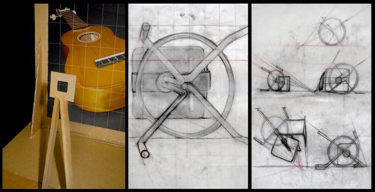
Reference planes in 3D modeling
Orthographic drawings — top, side, front, back, or a combination — are imported into camera views in the modeling program to create Reference or Image Planes. These can be manipulated to a proper scale. Here we see an illustration of the process of organizing a series of architectural drawings into third-angle projection. This is an organization that can also be created for drawings of figures, vehicles, or other objects. In the example, key projection lines are created or highlighted in red. These can be used to size and align the drawings in image planes:
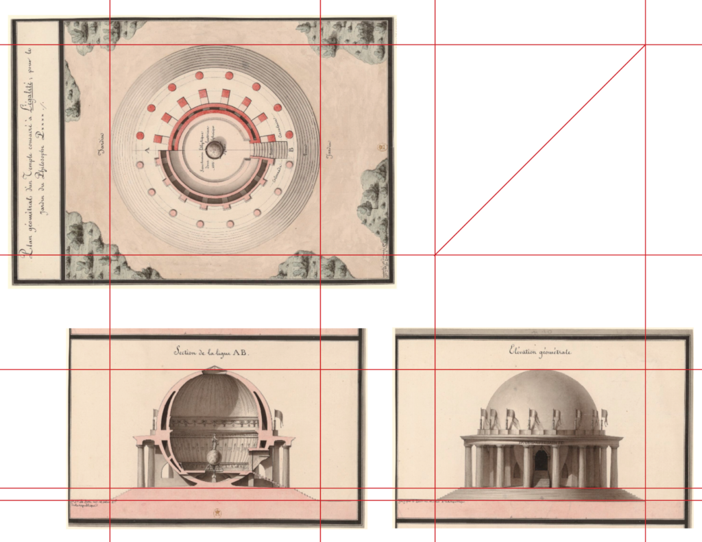
Orthographic third angle organization for an architectural object. The plan is at top left. The red lines are created to indicate alignments — of the plan with the section below, of the section with the front view, etc. This organization was created in Photoshop from images of original drawings by Jean Jacques Lequeu for A Temple Dedicated to Equality, For the Garden of the Philosophy, circa 1850.
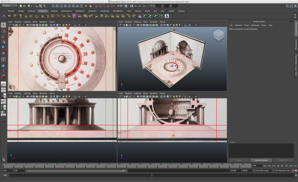
The drawings are separated and imported into image planes, where they can be sized and organized to the grid. The standard 4-view viewport preset can be used to create the proper top-front-side projection alignments.
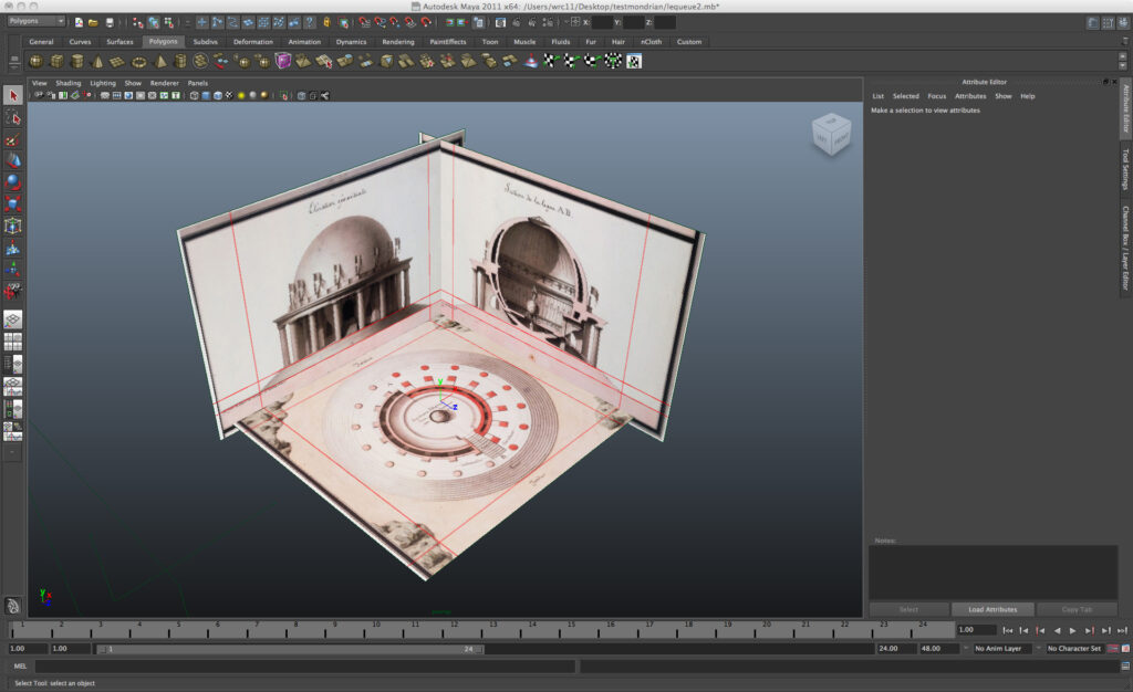
View of the perspective viewport shows how the images are organized in order to model the building. Toggling back and forth between single and multiple parallel and perspective views is a common method to create an accurate model.